
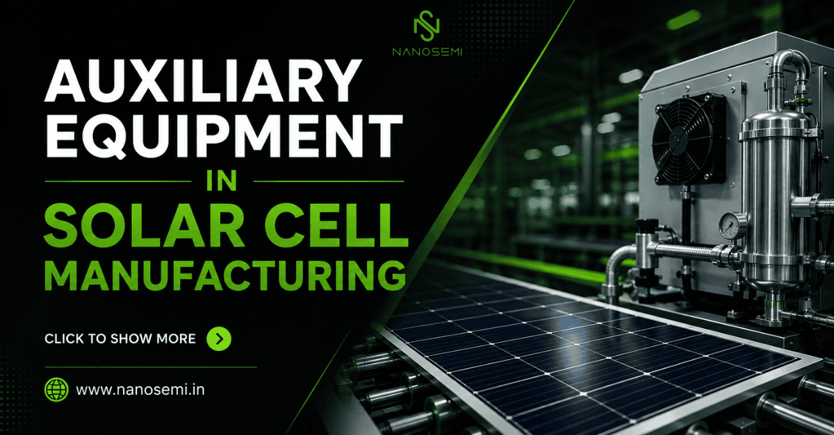
A detailed technical overview of five key auxiliary tools that ensure precision, operational efficiency, and quality control across the photovoltaic cell production line.
| 5 AUXILIARY SYSTEMS | ~30% YIELD IMPACT FROM AUXILIARY QC |
In the production of crystalline silicon solar cells, front-end processes like diffusion and passivation often receive the most attention. Yet the auxiliary equipment — responsible for paste management, cell handling, screen maintenance, metallization, and final packaging — plays an equally decisive role in achieving throughput targets, reducing wastage, and maintaining electrical performance uniformity. This blog provides an in-depth technical look at five critical auxiliary systems used on the modern solar cell production line.
01 / 05
Auxiliary Unit 01
Silver & Aluminum Paste Mixtures
Metallization Paste Preparation & Management System
Silver and aluminum conductive pastes are the cornerstone of solar cell metallization. Silver paste is screen-printed on the front side to form the finger and bus-bar grid that collects minority carriers generated in the n-type emitter layer, while aluminum paste is applied to the entire rear surface to form the back surface field (BSF) — a p⁺ layer that suppresses recombination and enhances open-circuit voltage.
| FRONT SILVER AG CONTENT | REAR AL CONTENT | VISCOSITY RANGE | FIRING TEMP (PEAK) |
| 88–95 wt% | 65–80 wt% | 100–400 Pa·s | 780–870 °C |
Modern paste preparation systems use planetary centrifugal mixers to homogenize the metallic flakes, glass frit (for adhesion and contact formation), organic binders, and solvents. Precise viscosity control — monitored inline with rotational viscometers — is critical, as deviation beyond
±5% of target viscosity will alter print line width, print resolution, and ultimately the fill factor of the finished cell.
“The quality of silver paste directly governs finger conductivity and fire-through performance. A well-mixed, properly characterized paste reduces contact resistance, one of the dominant loss mechanisms in high-efficiency cells.”
- Planetary mixing at 800–2000 rpm ensures uniform dispersion of silver flakes and prevents agglomeration that leads to finger breaks during printing.
- Inline viscosity monitoring systems flag out-of-spec batches before they reach the printer, preventing yield loss across entire production lots.
- Temperature-controlled storage (typically 4–10 °C) slows solvent evaporation and organic degradation, extending paste pot life from hours to several days.
- For aluminum paste, particle size distribution control (D50 typically 3–8 µm) determines the quality and uniformity of the BSF layer formed during co-firing.
02 / 05
Auxiliary Unit 02
Screen Wiping Robot
Automated Screen Cleaning & Maintenance System
Screen printing is the dominant metallization method for crystalline silicon solar cells. Screens — typically fabricated from stainless steel mesh stretched over an aluminum frame and coated with an emulsion — gradually accumulate paste residue that clogs mesh openings, alters open-area ratio, and degrades print quality over time. The screen wiping robot automates the cleaning cycle, eliminating a traditionally manual, inconsistent, and solvent-intensive process.
| CLEAN CYCLE TIME | WIPE INTERVAL | SCREEN MESH COUNT | SOLVENT USAGE REDUCTION |
| 15–45 seconds | Every 50–200 prints | 325–400 TPI | Up to 60% vs manual |
The robot uses a precision-controlled wiper blade — typically polyurethane or PTFE — that traverses the underside of the screen mesh in a programmed pattern. A metered solvent-dampened wipe cloth (often isopropanol or a proprietary paste solvent blend) removes wet paste without smearing dried residue back into open mesh areas. The system then performs a dry wipe to prevent solvent carry-over that could dilute subsequent paste prints.
Advanced systems integrate machine-vision inspection post-wipe, capturing a high-resolution image of the screen mesh and emulsion to identify partially blocked openings, emulsion delamination, or mesh wire breakage — conditions that would otherwise only be detected after printing defective cells.
“Consistent screen maintenance directly controls finger width uniformity. A 5 µm increase in average finger width due to clogged mesh translates to measurable shading losses, reducing Jsc and ultimately the cell’s power output.”
- Programmable wipe frequency, pressure, and speed allow optimization per paste formulation and screen mesh specification, preventing over-cleaning that can damage the emulsion layer.
- Automatic solvent metering ensures consistent wipe quality across shifts and operators, removing human variability as a process input.
- Integration with the screen printer PLC enables the robot to initiate cleaning cycles autonomously when print inspection feedback reports widening line width trends.
03 / 05
Auxiliary Unit 03
Auto Silver Filling Machine
Automated Paste Dispensing & Screen Refill System
The auto silver filling machine addresses one of the most deceptively impactful auxiliary functions on the cell line: ensuring that the screen printer always has the correct volume and distribution of silver paste on the print screen. Manual refilling introduces variability in paste bead size, placement, and temperature, all of which affect squeegee dynamics and therefore print quality.
| DISPENSING ACCURACY | FILL INTERVAL TRIGGER | PASTE TEMP CONTROL | CARTRIDGE CAPACITY |
| ±0.05 g per fill | Weight or vision-based | ±1 °C of setpoint | 200–600 g |
The machine uses a precision syringe or auger-based dispensing head mounted on a servo-controlled gantry. It deposits a controlled bead of silver paste — typically 5–20 g per refill event — in a defined position ahead of the squeegee travel zone. Some advanced systems continuously monitor paste bead height and width via a laser profilometer and supplement the bead in real time to maintain constant squeegee contact geometry throughout the print stroke.
Paste conditioning is an equally important function: the machine maintains the cartridge at a controlled temperature (typically 20–25 °C) to keep viscosity within the optimal printing range. Cold paste is too viscous and causes screen stretch and poor mesh penetration; warm paste is too fluid and bleeds under the screen, widening fingers and reducing aspect ratio.
“In high-speed production at 4,000+ wafers per hour, a manual refill cycle of even 30 seconds introduces both a line stop and a quality perturbation. The auto filling machine eliminates both, contributing directly to OEE improvement.”
- Vision-based paste bead monitoring detects insufficient volume before a print cycle begins, preventing starved prints that produce broken or under-width fingers.
- Automated cartridge exchange mechanisms allow operators to swap depleted cartridges without stopping the printer, maintaining continuous production flow.
- Data logging of paste consumption per print lot allows correlation with electrical performance data, supporting root-cause analysis of efficiency drift events.
04 / 05
Auxiliary Unit 04
Cell Shrink Wrap Packaging Machine
Automated Cell Protection & Final Packaging System
The cell shrink wrap packaging machine represents the final protective step before solar cells leave the manufacturing facility and enter the module assembly supply chain. Finished and sorted cells are mechanically fragile — a 166 mm or 210 mm monocrystalline wafer is typically only 160–180 µm thick — and are highly susceptible to moisture absorption, electrostatic discharge, and particulate contamination. Shrink wrapping provides a hermetic, static-dissipative barrier that protects cells during transit and storage.
| PACK THROUGHPUT | STACK COUNT PER PACK | FILM TYPE | SHRINK TEMP RANGE |
| Up to 6,000 cells/hr | 25, 50, or 100 cells | ESD polyolefin 40–60 µm | 120–160 °C |
Cells are stacked in pre-defined counts — commonly 25, 50, or 100 per package — with interleaf separator sheets made from anti-static, lint-free foam or tissue to prevent edge-to-edge contact and chip damage. The stacking robot uses vacuum end-effectors with controlled placement force to prevent micro-cracking events. The assembled stack is then conveyed into the shrink tunnel where biaxially oriented polyolefin film conformally wraps around the stack and heat-shrinks to form a rigid, tight bundle.
Anti-static and moisture-barrier properties of the film are rigorously specified: surface resistivity is typically maintained in the 10⁶–10¹¹ Ω/sq range (static-dissipative) to prevent ESD damage to the silver contact structures, and water vapor transmission rate (WVTR) below 5 g/m²/day ensures cells remain protected even in humid storage environments.
“Micro-cracking during packaging is one of the leading causes of latent field failures in PV modules. Cells that pass electrical testing but carry sub-visible cracks from handling can delaminate under thermal cycling, creating hot spots and accelerated degradation.”
- Automated labelling systems apply barcode or QR-coded lot ID labels to each package, enabling full traceability from the finished module back to the individual cell production lot and paste batch.
- Vision inspection at the stacking stage detects misaligned or inverted cells before packaging, preventing the costly need to re-open and re-sort completed packs downstream.
- Nitrogen purge options (available on premium machines) replace ambient air inside the package with inert N₂ gas, providing additional protection against silver contact oxidation during long-term storage or ocean freight.
- Package integrity sensors monitor seal quality using pressure differential testing, rejecting packs with incomplete seals that could allow moisture ingress during transport.
05 / 05
Auxiliary Unit 05
Solar Cell Counters
Automated Cell Counting, Batching & Production Tracking System
Purpose of Solar Cell Counters
Solar cell counters are automated devices used for accurate counting, batching, and tracking of solar cells during production and packaging operations. As solar manufacturing lines operate at extremely high throughput, manual counting becomes impractical and error-prone.
Solar cell counters help manufacturers:
- Improve inventory accuracy
- Prevent handling damage
- Enable automated packaging
- Maintain production traceability
Operating Principle
These systems use optical sensors, vision systems, conveyor synchronization, and edge detection technology to detect and count individual solar cells moving through the production line.
- Optical sensors detect cell presence and passage in real time, enabling precise count increments without physical contact.
- Vision systems verify cell orientation, surface integrity, and lot consistency at the point of counting, combining quality control with enumeration.
- Conveyor synchronization links counter data with line speed, ensuring batching targets are met even at throughputs exceeding 6,000 cells per hour.
- Edge detection technology distinguishes individual cells from closely spaced groups, preventing miscounts caused by overlapping or near-adjacent wafers on the conveyor.
INDUSTRY CONTEXT …. Industry Outlook
The Growing Importance of Auxiliary Automation
Why supporting systems matter more than ever
As the solar industry accelerates toward higher wafer sizes, thinner wafers, advanced cell architectures, and gigawatt-scale factories, the role of auxiliary equipment has shifted from support function to strategic necessity. Technologies such as TOPCon and HJT demand tighter process tolerances and more delicate handling than conventional PERC — conditions where manual or semi-automated auxiliary processes simply cannot deliver the consistency required.
| WAFER TREND | THICKNESS TREND | FACTORY SCALE | CELL TECHNOLOGY |
| 166 → 210+ mm | 180 → 140 µm | GW-class lines | PERC/TOPCon / HJT |
Modern solar manufacturing is no longer dependent only on primary process tools. Supporting automation systems now play a crucial role across five key dimensions of production excellence:
- Yield enhancement — Tighter paste control, consistent screen cleaning, and precision packaging directly reduce material loss and defect-driven cell rejection rates.
- Process stability — Automated auxiliary systems eliminate operator variability across shifts, maintaining consistent process inputs that primary tools depend on.
- Cost reduction — Optimized paste consumption, reduced rework, and lower scrap rates translate into measurable cost-per-watt improvements at scale.
- Smart manufacturing — Auxiliary systems equipped with inline sensors and data logging generate rich process datasets that feed machine-learning models and SPC systems.
- Industry 4.0 integration — Modern auxiliary equipment communicates via MES/SCADA interfaces, enabling end-to-end digital traceability from paste batch to finished packaged cell.
“Manufacturers investing in robust auxiliary systems gain significant advantages in operational efficiency and product quality — advantages that compound as production volumes scale and cell technology complexity increases.”
Conclusion
Auxiliary equipment forms the backbone of efficient and reliable solar cell manufacturing operations. Systems such as paste mixers, screen wiping robots, auto silver filling machines, and shrink wrap packaging machines ensure stable production, minimize defects, and optimize throughput.
In today’s competitive photovoltaic industry, where every fraction of efficiency matters, these support technologies contribute directly to manufacturing excellence and commercial success.
As solar production technology advances further, auxiliary automation will continue evolving toward:
- AI-driven monitoring and real-time process optimization
- Predictive maintenance to eliminate unplanned downtime
- Fully autonomous operation with minimal human intervention
- Smart factory integration across the entire PV value chain
Making them indispensable components of next-generation solar manufacturing facilities.
@ Nanosemi, we provide best in class auxiliary equipment’s with proven track record in the factory. Connect us to know more.
To know more please connect here
Author: Jitendra Singh | jitendra@nanosemi.in | +91-9560 265963